20100818
The plan
Build a superheterodyne radio using one passive and one active mixer, using the dead bug construction method and testing each part in turn.
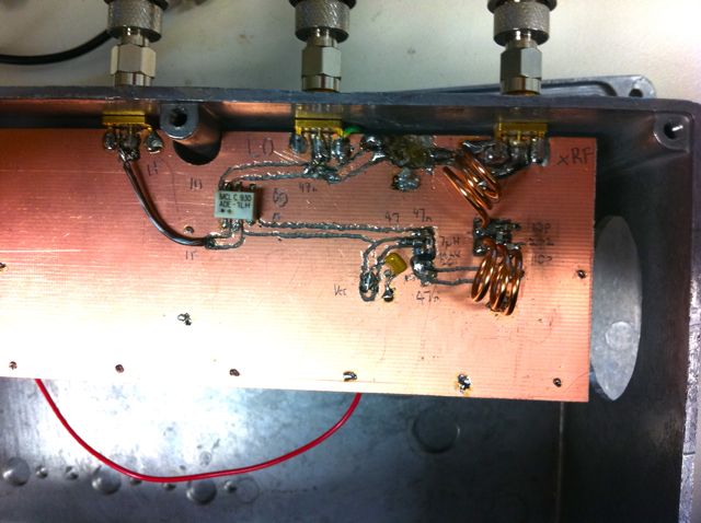
Circuit under test
The first filter
Uses two 2.5 turn tapped inductors and three capacitors, values determined to be 10pF/10pF/2.2pF (chip capacitors) or 10pf/10pF/1.8pF (ceramic with long legs and large PCB pads). Shown here is the second attempt, using chip capacitors, which seems to have flattened the response a bit over the early leaded attempt.
Transfer function of 150 MHz bandpass filter, based on Industrial Communication Engineers bandpass filter.
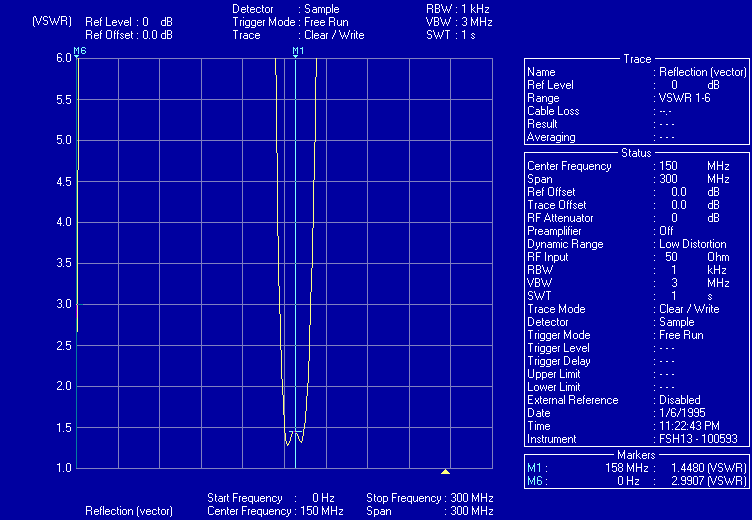
VSWR of 150 MHz bandpass filter, based on Industrial Communication Engineers bandpass filter.
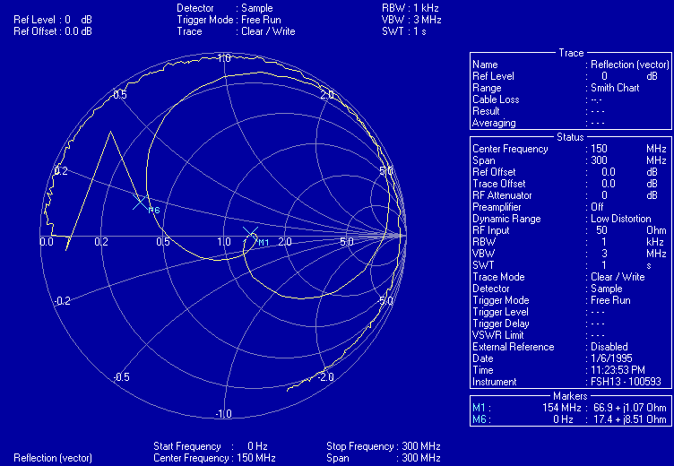
Smith chart of 150 MHz bandpass filter, based on Industrial Communication Engineers bandpass filter.
The LNA
MAX2611 and GVA-84+ amplifiers were tested, but it was determined that the performance of the MAX2611 was adequate, and at 25 mA compared to 100 mA, it is preferable!
The first mixer
An ADE-1LH+ mixer was used, with the 10 dBm drive provided by a signal generator at 100 MHz.
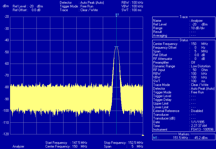
RF input was provided by a Si520 osciilator, set here to 151.5 MHz. 40 dB of attenuation was connected inline, giving an input to the LNA of -45.2 dBm
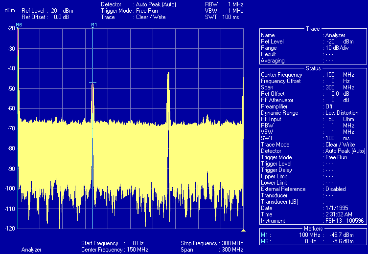
Local oscillator products (50 MHz and 200 MHz) with no RF input.
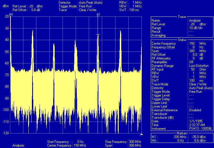
All mixer outputs from 0 to 300 MHz, showing all products.
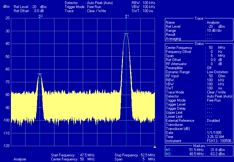
Well, the system gain looks okay. Mixer outputs from 42.5 to 52.5 MHz, showing downmixed signal at 51.5 MHz, -31.8 dBm, and corresponding other output at 48.5 MHz,-63.2 dBm.
This points to a poor choice of IF! The lower peak is 2*LO - RF. A better LO and IF needs to be picked.
