20100727
It took many attempts, but I eventually managed to produce a circuit board for my ADC. The PulsarProFX system had a couple of issues:
- My printer smudged very fine tracks in one direction, but not the other
- The toner transfer step worked reasonably well
- The green TRF step also smudged
Ahmad from Ultrakeet very helpfully suggested putting some tape over the smudged tracks, rubbing it down, then peeling away slowly. This worked very well! It looks like the green TRF's green stuff had trouble sticking to the plastic backing when the track to track width was very small, but the tape pulled it away but left the TRF attached to the toner. A small problem with this approach was that my printer doesn't do solid blacks very well, so when I taped the polygon fill areas it pulled some of that away too. Not a big deal, but it makes it look a bit unattractive.
The next step was to assemble it in stages! The power supply was okay except that I screwed up the pin assignment on one of the LDO regulators. Not to worry though, I could just rotate the part and it all still lined up appropriately. I had *loads* of trouble soldering the TSOP differential amplifier chip. It's fortunate that I have four input channels, because I ruined the PCB tracks on one of them completely (and the copper on some of the others looked iffy).
After fixing many bridges and straightening the pins, I got some results:
Input: HP 8782A signal generator, 2 MHz at -35 dBm Measured input (single ended): Vpp = 12.8 mV Measured output 1: Vpp = 164 mV Measured output 2: Vpp = 24 mV
I have no idea why the differential outputs would be so different! I'd assumed they'd be the same but inverted, or something. Using two probes and A-B.. Well, my DSO's math function is a bit confusing - it looks like it's just under 200 mV p-p according to the scale but that doesn't seem right based on the input voltages! Anyway, the gain seems pretty decent, at about 22 dB on one channel, and who knows for the differential.
I presume the result is something to do with the way that the single-to-double configuration works.
Next step is to make a new board! Some minor revisions - fix the LDO pin assignment, and add a nice power LED, something that I always forget to do. Nothing worse than a fancy board that does absolutely nothing when you power it up!
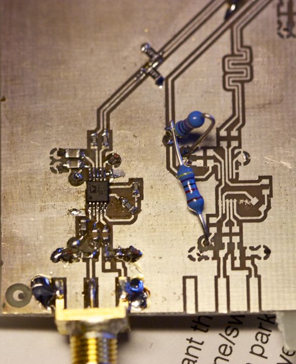
Pictured: differential amplifier. The axial resistors are voltage divider providing a common mode voltage, which would normally be generated by the ADC if it were installed.
